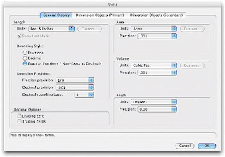
All of these can be set from one central place. Go to File > Document Settings > Document Setup.
Units
Vectorworks enables users to use whatever units they prefer. The most common units such as millimetres and feet / inches are predefined but users can also create their own units. The vast majority of CAD users in the UK use millimetres. Set the unit type to millimetres by picking it from the pull-down list and ensure display as decimal is selected.


Scale
When you draw objects in Vectorworks they are drawn at full-size but displayed on screen (and printed) to scale (known as paper scale). When a new Vectorworks document is created a default sized piece of paper (usually A4) is represented on screen and the default paper scale (usually 1:1 or 1:50) is automatically used.
NB: In Vectorworks you have the flexibility of setting one scale for all the layers in your drawing, or setting a different scale for individual layers. This enables printed drawings to have elements at different scales (maybe a detail at 1:10 and a plan at 1:50).

Paper size
Go to the Menu Bar and choose File > Page Setup. Next, click on the Printer Setup button and choose the settings for your printer. Click on the OK button and then check the Page Setup. You should have one page horizontal and one page vertical.
Here we can specify the size (A3, A2 etc) and orientation of your document (Portrait or landscape). To specify a paper size when printing, Vectorworks enables smaller sheets of paper to be tiled together in order to create large drawings.

Set Grid
Vectorworks drawing is done to a pre-set grid of points and lines on the page that can be changed at any stage .
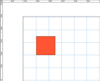
The Reference grid is shown as blue vertical and horizontal lines on the page which can never be smaller in interval than the snap grid.
The Reference lines correspond to the rulers running along the top and left edge of the page, starting from lines at X=0 and Y-0 and then repeated at your pre-set intervals.
By default the Reference lines will not print with your work. This can be changed through the Set Grid dialogue box, a really useful option if you wish to draw over any printed plans for example.
The snap grid consists of points that can be set to any level of interval from 0.1mm up to 10000mm and beyond.
The Snap Grid limits the freedom of any drawing to that selected grid. This is really useful for drawing to standardised measurements and limit’s the need to edit object dimensions after drawing. Select the appropriate snap grid for the task in hand. You can alter the grid settings during a project and this will not affect any objects drawn.

Reference Grid = 1000mm / Snap Grid = 500mm
No comments:
Post a Comment