Saturday

8. Viewports and Sheet Layers

Once you have a model you will need to present it. Vectorworks has what are called Viewports and Sheet Layers in which to do this (like architectural technical drawing layouts).

Viewport Creation

To create a Viewport select the objects that are to be presented and go to View - Create Viewport. The objects are then re-presented on a new 'Sheet Layer' as 2D Viewports. We can create as many sheets as we need.

You can create a Viewport from any Standard View, in any scale, render or even in Perspective.  

You can take as many Viewports through to a sheet as you wish, although sometimes it is easier to simply take one through and then copy/duplicate it as many times as needed as we can always change their settings afterwards. (Hold down alt to copy and drag!)

Editing Viewports


Once in the Sheet Layer, Viewports can be edited through the Object Info Pallette

We can change the view, scale, render and perspective of a particular viewport. 

The Viewport may need to be updated afterwards if a red line appears around it, to do this go to View - Update Viewports (or select Update in the Obj. Info Palette).

By double-clicking on a Viewport you can edit it further, either by adding annotations, dimensions or by cropping (useful for showing design details and framing perspective views).
  • Anotations can include all textual notes as well as any extra 2D line/shape work that needs to be added over the top of a viewport.
  • Dimensions should only be added within the viewport, adding them to the Sheet Layer will create them to the Layers paper scale (1:1) and not the viewports scale.
  • Crops are created using any 2D Shape (circles, rectangles or polygons/polylines etc). Sometimes you may wish to have a borderless crop, simply set the Pen Line setting to none for the Crop Object.

Arrange your sheet layers like architectural layout pages with your plan bottom left and elevation directly above. We can add a drawing border and title block in the bottom right hand corner (Tool Sets Palette > Dimensions and Notes).

As well as using Vectorworks own Page Layout Tools it is often a more exciting Graphic approach to add in your own layout elements. 


Try adding Text for Titles, 2D Shapes for backgrounds or even import Images and Photographs to use in your Presentation Pages.

Tip: The adding of text and Images from other packages (Word, Works etc, or even straight from the Web) can be done simply by copying and pasting into the Sheet Layer. This makes it quick and easy to anotate your work.


As you continue to work on your model the sheet layers will automatically update!


Plan:

Note that often though you will be better off producing plans using 2D tools and keeping them separate from the 3D model (each case is different, just make sure that the plan is clear and easy to read). You may have to combine 2D, 3D and Hybrid Objects to achieve the best result.

_____________________________________

Monday

Showcase

Presentation

Exercises

Christopher Wray Lighting Model
The first exercise will be the production of a piece of lighting from the online range from designer Christopher Wray.

  • Download the Image File to your 'DMAE Folder', and make a note of the Specification and fabrication details.

  • Open up Vectorworks and follow the worksheet shown below.

Tools

By far the most enjoyable tool to use for the first time is the Sweep Tool. Sweeps include tables, stools, glasses or bottles and even whole buildings!.

Sweep Tool :

  • This tool works by drawing half of an objects profile and sweeping this around its center (we always draw the right hand side of the objects profile). It is often useful to draw a vertical line to act as a guide to draw to, this can be deleted later before activating the sweep command.


  • Sweeps can consist of individual lines, 2D Primitive shapes and multiples of both.


  • Sweeps are made up of Segments, each segment has a degree value. By adding segments we can make them smoother in appearance (the smoothest being 0.1). By decreasing the segments we can turn them into sweeps of different shapes . Four segments of ninety degrees will create square sweeps!This makes the sweep tool ideal for quickly trying out different design ideas for say a table.


  • For more advanced sweeps we need to include what is termed a 2D Locus Point. We can place this wherever we want and this will now become the sweeps center of rotation. This creates sweeps with space at their centers (such as a bar counter or information desk).


  • The sweep tool can be set to rotate through any number of degrees (either less or more than 360). A sweep of 180 degrees will result in half a swept profile. A sweep of 330 degrees will produce a bar counter with an access point!


  • By adjusting the sweeps Pitch higher and the rotation above 360 we can create spiralling sweeps. For example if we sweep a circle with a diameter of 100mm and an off-set 2D locus we will get a dough-nut shape as a result. By changing the pitch to say 150mm and the sweep to 3600 degrees we will get a spring!

Finally we should look at editing sweeps.

  • We can double-click on a sweep to add to, delete from or edit the original. Click on 'Done' to see the updated result.

  • By un-grouping a sweep (Modify> Un-Group) made from multiple shapes we can then apply individual textures to each sweep as well as adjusting the settings for each one.

It is amazing how this tool will cut down the time needed for modeling complex schemes and how it can be used to make shapes that at first will not be obvious to you!

Session 7 : Sweeps

-------------------------------------------------------------------

Extra Exercise: Skysraper Challenge

As an extra task this week, if you wish to except it, we are going to do a quick exercise to design a most visually astounding skyscraper!

Try to incorporate....

1) The Multiple extrude Tool
2) Advanced Duplication using 'Rotate Duplicates'
3) The use of Symbols
4) Dynamic Saved Views to present the model
5) The Render Bitmap Tool to document the development.
6) Even an Animation of the final Structure!

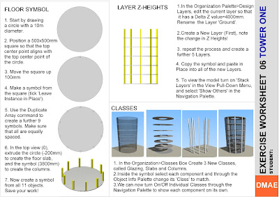
Exercise 06: Tower One

This sessions exercise is designed to teach you how to set up and organize a model of a multi-story building. It shows how we can use duplicates and symbols to quickly construct the structure and layers and Classes to efficiently organize and present the outcome.

The aim is to follow the worksheet below and then to take the model on further by adding your own individual components.


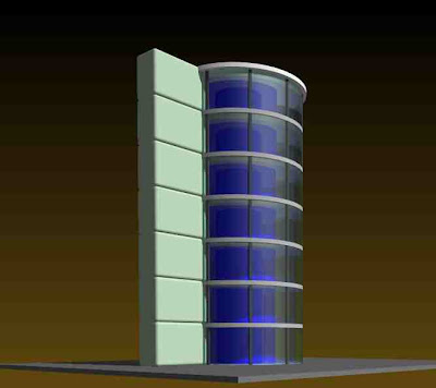
Below are some renders of the model with the addition of a Renderworks background and a variety of Light sources.

____________________________________

Exporting From Vectorworks

One way of getting your drawing/model from vectorworks is to print straight from the program. Alternatively we can export out the information as still images. these can then be printed, re-sized, emailed etc.

Exporting to Scale:
  • To export your drawing or model to scale go to; File> Export> Export Image File

Now we can select 'Each Page as seperate Image'. This means that only what is inside the page boundary will be exported and that it will be exported at the pre-set page size automatically.

We still have to set the resolution and file type (for line drawings 240dpi should be sufficient).

  • Another way to export to scale is as a PDF Document, go to File> Export> Export PDF

This will again export what is inside the page boundary only (the default resolution of 300dpi is used). PDF documents export line drawings at a better quality than other export file types and produce more accurate line thicknesses.


Exporting in Perspective:

To export one of your saved views (or any other perspective view) go to;

File> Export> Export Image File

Here we can ask the computer to render and export 'Current view', this will export only what is contained with-in the viewing space. You should therefore compose the dimension of the export first and frame it on the screen using the zoom tools. Also note that it will export in whichever render mode you have on the screen.

Resolution:
Depending on the time available and the use of the render we can export out at any given resolution. For good quality renders I suggest at least 200dpi. for line work at least 150dpi.

The best thing to do is to test the quality for each model. the more lights and textures that you have the longer the render is going to take. it is not unusual for some renders to take as long as 1 hour!

Print Size:
Here we can set the export print size. As the ratio is already set in the saved view we only need to input a value for either width or height not both (e.g 420mm width for an A3 landscape export).

File type:
Select from a wide range of file types. I suggest jpeg or tiff for now.

When you have set all of the required fields, click save and give the render a name and select where to save to.

Working with Classes in 3D

Z-Heights and Stacking Layers


Creating Copies, Duplicates and Symbols

Copying and Pasting
Often in Vectorworks you will need to copy single or multiple objects, this is a simple and often used feature of most graphic packages and works generally the same.

In the Edit Menu you will find the Copy, Paste and Paste in Place commands.

Once you have copied an object the computer will store the information until it has been told to copy something else. Once you have pasted the object you can carry on pasting the object as many times as you wish. It will place the copy on the screen fairly randomly.

The Paste in Place command pastes the object into exactly the same place as the original. This is especially useful when working between layers or even files. It is also useful when copying and pasting into and out of a 3D object or group.

Duplicates
You can make a single duplicate of a 2D/3D object by using Edit> Duplicate command. It may be useful to turn off off-set duplications in Vectorworks Preferences first so that the duplicate is placed in the same position.

The Edit > Duplicate Array command has three extra modes of duplication which all have their specific uses, (Linear, rectangular and circular). These work by imputing data for movement in x,y and z co-ordinates. You can also specify the number of Duplicates to be created.

You can duplicate multiple objects at the same time. After carrying out a duplicate array it is often useful to group the results so that they can be selected, moved etc with ease (Edit>Group).

Symbols 1:
When making duplicates it often makes sense to make a symbol (Modify> Create Symbol) out of the object first. This means that you can edit one symbol and it will update the rest automatically. When creating a symbol remember to tick the ‘Leave Instance in place box’ otherwise your symbol will be placed into the Resource Browser.

Any object that will be repeated throughout your model should be made a symbol (Chairs, tables, taps, floortiles, pillars etc.). You can even make symbols out of multiple objects (say a bedroom scheme for a 200 room hotel!). This way you can come up with large design schemes fairly quickly and update your scheme as your design develops with limited remodeling required.

We will be using symbols in more detail in later sessions so do not worry too much if it seems confusing to begin with!

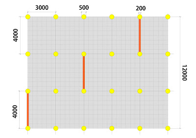
Exercise : 2D Duplication

-Draw out the plan below using the Duplicate Array Tool (consider the different modes of Duplication.


-Before Duplicating create symbols out of each component part.

-Once Created Create a New Class (Tools > Organization > Classes > New) for each Symbol and assign through the Object Information Palette.

-Turn On/Off Class Visibilities through the Navigation Palette to show the Drawing in diffferent levels of detail.

SESSION 6 : LAYERS, CLASSES, SYMBOLS

SESSION 6: Checklist

Resources
DMAE Blog notes (Session 6)
Exercise Worksheet
Demonstration Vectorworks File

Extrusions
Multiple Exrudes
Editing Multiple Extrudes

Duplicates
Off-set Duplicate Settings
Single Duplicates
Linear Duplication
Rectangular Duplication
Circular Duplication
Rotating and Re-Sizing Duplicates
Grouping Duplicates

Creating Symbols
Creating Symbols from single object
Creating Symbols from multiple objects
Editing as 2D and 3D Symbols
Un-Grouping Symbols

Working with Layers 3
Setting Layer Z-Heights
Copying between Layers (Symbols)
Stacking Layers

Working with Classes
Assigning Classes to Objects
Using Class Visibilities
Using Classes with Saved Views

Visualisation
Re-Cap on navigation
Revision of previous Rendering notes
Applying Backgrounds
Textures: Steel, Glass and Concrete
Adding a Sun Object
Day / Night Renders

Outcomes
Exported set of Perspectives

_____________________________________