Monday
Session 9 : NURBS Experiments
DAY FIVE: Checklist (ADVANCED 3D MODELLING)
Resources:
DMAE Blog and Internet sites
Vectorworks Help Menu
Worksheets
Drawing NURBS Curves:
Composing 2D Paths
Converting Paths/Shapes to NURBS
Using the NURBS Curve/Circle/Arc Tools
Editing NURBS Curves
Loft Surface Tool:
Arranging the NURBS Curves
Loft Surface Preferences
Shelling Loft Surfaces (for thickness).
Interpolated Surfaces:
Drawing the Surface
Setting U / V Values
Moving Entire Object and Individual Vertices (Object Info)
Editing Manually with Mouse
Extracting Curves:
Extract Tool Preferences
Extruding Along NURBS Paths
Animations:
Creating Orbit animations
Creating Animations Along Paths
Saving/Viewing Animations
Compiling Work:
Re-Cap on Sheet Layers
Re-Cap on Session Outcomes/Exercises
Re-Cap on Exporting Settings
Compiling as one Course PDF
Hand-In
Extras:
Other Compatible Software (Import/Export)
Further Study at LCC
Saturday
8. Viewports and Sheet Layers
 Once you have a model you will need to present it. Vectorworks has what are called Viewports and Sheet Layers in which to do this (like architectural technical drawing layouts).
Viewport Creation
To create a Viewport select the objects that are to be presented and go to View - Create Viewport. The objects are then re-presented on a new 'Sheet Layer' as 2D Viewports. We can create as many sheets as we need.
You can create a Viewport from any Standard View, in any scale, render or even in Perspective.
You can take as many Viewports through to a sheet as you wish, although sometimes it is easier to simply take one through and then copy/duplicate it as many times as needed as we can always change their settings afterwards. (Hold down alt to copy and drag!)
Editing Viewports
Once in the Sheet Layer, Viewports can be edited through the Object Info Pallette.
We can change the view, scale, render and perspective of a particular viewport.
The Viewport may need to be updated afterwards if a red line appears around it, to do this go to View - Update Viewports (or select Update in the Obj. Info Palette).
By double-clicking on a Viewport you can edit it further, either by adding annotations, dimensions or by cropping (useful for showing design details and framing perspective views).
- Anotations can include all textual notes as well as any extra 2D line/shape work that needs to be added over the top of a viewport.
- Dimensions should only be added within the viewport, adding them to the Sheet Layer will create them to the Layers paper scale (1:1) and not the viewports scale.
- Crops are created using any 2D Shape (circles, rectangles or polygons/polylines etc). Sometimes you may wish to have a borderless crop, simply set the Pen Line setting to none for the Crop Object.
Arrange your sheet layers like architectural layout pages with your plan bottom left and elevation directly above. We can add a drawing border and title block in the bottom right hand corner (Tool Sets Palette > Dimensions and Notes).
As well as using Vectorworks own Page Layout Tools it is often a more exciting Graphic approach to add in your own layout elements.
Try adding Text for Titles, 2D Shapes for backgrounds or even import Images and Photographs to use in your Presentation Pages.
Tip: The adding of text and Images from other packages (Word, Works etc, or even straight from the Web) can be done simply by copying and pasting into the Sheet Layer. This makes it quick and easy to anotate your work.
As you continue to work on your model the sheet layers will automatically update!
Plan:
Note that often though you will be better off producing plans using 2D tools and keeping them separate from the 3D model (each case is different, just make sure that the plan is clear and easy to read). You may have to combine 2D, 3D and Hybrid Objects to achieve the best result.
Monday
Exercises
Christopher Wray Lighting Model
The first exercise will be the production of a piece of lighting from the online range from designer Christopher Wray.
The first exercise will be the production of a piece of lighting from the online range from designer Christopher Wray.
- Visit the link below and choose a piece that you would like to model (make sure that it involves the use of the Sweep Tool!).
http://www.christopherwray.com/product/productgroup.asp?GP=TB
- Download the Image File to your 'DMAE Folder', and make a note of the Specification and fabrication details.
- Open up Vectorworks and follow the worksheet shown below.
Tools
By far the most enjoyable tool to use for the first time is the Sweep Tool. Sweeps include tables, stools, glasses or bottles and even whole buildings!.
Sweep Tool :
Sweep Tool :
- This tool works by drawing half of an objects profile and sweeping this around its center (we always draw the right hand side of the objects profile). It is often useful to draw a vertical line to act as a guide to draw to, this can be deleted later before activating the sweep command.
- Sweeps can consist of individual lines, 2D Primitive shapes and multiples of both.
- Sweeps are made up of Segments, each segment has a degree value. By adding segments we can make them smoother in appearance (the smoothest being 0.1). By decreasing the segments we can turn them into sweeps of different shapes . Four segments of ninety degrees will create square sweeps!This makes the sweep tool ideal for quickly trying out different design ideas for say a table.
- For more advanced sweeps we need to include what is termed a 2D Locus Point. We can place this wherever we want and this will now become the sweeps center of rotation. This creates sweeps with space at their centers (such as a bar counter or information desk).
- The sweep tool can be set to rotate through any number of degrees (either less or more than 360). A sweep of 180 degrees will result in half a swept profile. A sweep of 330 degrees will produce a bar counter with an access point!
- By adjusting the sweeps Pitch higher and the rotation above 360 we can create spiralling sweeps. For example if we sweep a circle with a diameter of 100mm and an off-set 2D locus we will get a dough-nut shape as a result. By changing the pitch to say 150mm and the sweep to 3600 degrees we will get a spring!
Finally we should look at editing sweeps.
- We can double-click on a sweep to add to, delete from or edit the original. Click on 'Done' to see the updated result.
- By un-grouping a sweep (Modify> Un-Group) made from multiple shapes we can then apply individual textures to each sweep as well as adjusting the settings for each one.
It is amazing how this tool will cut down the time needed for modeling complex schemes and how it can be used to make shapes that at first will not be obvious to you!
Extra Exercise: Skysraper Challenge
As an extra task this week, if you wish to except it, we are going to do a quick exercise to design a most visually astounding skyscraper!
Try to incorporate....
1) The Multiple extrude Tool
2) Advanced Duplication using 'Rotate Duplicates'
3) The use of Symbols
4) Dynamic Saved Views to present the model
5) The Render Bitmap Tool to document the development.
6) Even an Animation of the final Structure!
Try to incorporate....
1) The Multiple extrude Tool
2) Advanced Duplication using 'Rotate Duplicates'
3) The use of Symbols
4) Dynamic Saved Views to present the model
5) The Render Bitmap Tool to document the development.
6) Even an Animation of the final Structure!
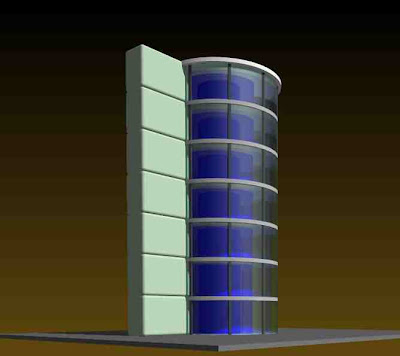
Exercise 06: Tower One
This sessions exercise is designed to teach you how to set up and organize a model of a multi-story building. It shows how we can use duplicates and symbols to quickly construct the structure and layers and Classes to efficiently organize and present the outcome.
The aim is to follow the worksheet below and then to take the model on further by adding your own individual components.
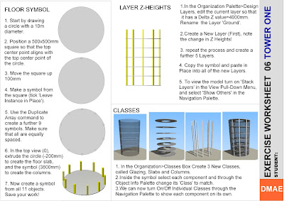
Below are some renders of the model with the addition of a Renderworks background and a variety of Light sources.

The aim is to follow the worksheet below and then to take the model on further by adding your own individual components.

Below are some renders of the model with the addition of a Renderworks background and a variety of Light sources.


Exporting From Vectorworks
One way of getting your drawing/model from vectorworks is to print straight from the program. Alternatively we can export out the information as still images. these can then be printed, re-sized, emailed etc.
Exporting to Scale:
Exporting in Perspective:
To export one of your saved views (or any other perspective view) go to;
File> Export> Export Image File
Here we can ask the computer to render and export 'Current view', this will export only what is contained with-in the viewing space. You should therefore compose the dimension of the export first and frame it on the screen using the zoom tools. Also note that it will export in whichever render mode you have on the screen.
Resolution:
Depending on the time available and the use of the render we can export out at any given resolution. For good quality renders I suggest at least 200dpi. for line work at least 150dpi.
The best thing to do is to test the quality for each model. the more lights and textures that you have the longer the render is going to take. it is not unusual for some renders to take as long as 1 hour!
Print Size:
Here we can set the export print size. As the ratio is already set in the saved view we only need to input a value for either width or height not both (e.g 420mm width for an A3 landscape export).
File type:
Select from a wide range of file types. I suggest jpeg or tiff for now.
When you have set all of the required fields, click save and give the render a name and select where to save to.
Exporting to Scale:
- To export your drawing or model to scale go to; File> Export> Export Image File
Now we can select 'Each Page as seperate Image'. This means that only what is inside the page boundary will be exported and that it will be exported at the pre-set page size automatically.
We still have to set the resolution and file type (for line drawings 240dpi should be sufficient).
- Another way to export to scale is as a PDF Document, go to File> Export> Export PDF
This will again export what is inside the page boundary only (the default resolution of 300dpi is used). PDF documents export line drawings at a better quality than other export file types and produce more accurate line thicknesses.
Exporting in Perspective:
To export one of your saved views (or any other perspective view) go to;
File> Export> Export Image File
Here we can ask the computer to render and export 'Current view', this will export only what is contained with-in the viewing space. You should therefore compose the dimension of the export first and frame it on the screen using the zoom tools. Also note that it will export in whichever render mode you have on the screen.
Resolution:
Depending on the time available and the use of the render we can export out at any given resolution. For good quality renders I suggest at least 200dpi. for line work at least 150dpi.
The best thing to do is to test the quality for each model. the more lights and textures that you have the longer the render is going to take. it is not unusual for some renders to take as long as 1 hour!
Print Size:
Here we can set the export print size. As the ratio is already set in the saved view we only need to input a value for either width or height not both (e.g 420mm width for an A3 landscape export).
File type:
Select from a wide range of file types. I suggest jpeg or tiff for now.
When you have set all of the required fields, click save and give the render a name and select where to save to.


Creating Copies, Duplicates and Symbols
Copying and Pasting
Often in Vectorworks you will need to copy single or multiple objects, this is a simple and often used feature of most graphic packages and works generally the same.
In the Edit Menu you will find the Copy, Paste and Paste in Place commands.
Once you have copied an object the computer will store the information until it has been told to copy something else. Once you have pasted the object you can carry on pasting the object as many times as you wish. It will place the copy on the screen fairly randomly.
The Paste in Place command pastes the object into exactly the same place as the original. This is especially useful when working between layers or even files. It is also useful when copying and pasting into and out of a 3D object or group.
Duplicates
You can make a single duplicate of a 2D/3D object by using Edit> Duplicate command. It may be useful to turn off off-set duplications in Vectorworks Preferences first so that the duplicate is placed in the same position.
The Edit > Duplicate Array command has three extra modes of duplication which all have their specific uses, (Linear, rectangular and circular). These work by imputing data for movement in x,y and z co-ordinates. You can also specify the number of Duplicates to be created.
You can duplicate multiple objects at the same time. After carrying out a duplicate array it is often useful to group the results so that they can be selected, moved etc with ease (Edit>Group).
Symbols 1:
When making duplicates it often makes sense to make a symbol (Modify> Create Symbol) out of the object first. This means that you can edit one symbol and it will update the rest automatically. When creating a symbol remember to tick the ‘Leave Instance in place box’ otherwise your symbol will be placed into the Resource Browser.
Any object that will be repeated throughout your model should be made a symbol (Chairs, tables, taps, floortiles, pillars etc.). You can even make symbols out of multiple objects (say a bedroom scheme for a 200 room hotel!). This way you can come up with large design schemes fairly quickly and update your scheme as your design develops with limited remodeling required.
We will be using symbols in more detail in later sessions so do not worry too much if it seems confusing to begin with!
Exercise : 2D Duplication
-Draw out the plan below using the Duplicate Array Tool (consider the different modes of Duplication.
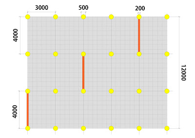
-Before Duplicating create symbols out of each component part.
-Once Created Create a New Class (Tools > Organization > Classes > New) for each Symbol and assign through the Object Information Palette.
-Turn On/Off Class Visibilities through the Navigation Palette to show the Drawing in diffferent levels of detail.
SESSION 6 : LAYERS, CLASSES, SYMBOLS
SESSION 6: Checklist
Resources
DMAE Blog notes (Session 6)
Exercise Worksheet
Demonstration Vectorworks File
Extrusions
Multiple Exrudes
Editing Multiple Extrudes
Duplicates
Off-set Duplicate Settings
Single Duplicates
Linear Duplication
Rectangular Duplication
Circular Duplication
Rotating and Re-Sizing Duplicates
Grouping Duplicates
Creating Symbols
Creating Symbols from single object
Creating Symbols from multiple objects
Editing as 2D and 3D Symbols
Un-Grouping Symbols
Working with Layers 3
Setting Layer Z-Heights
Copying between Layers (Symbols)
Stacking Layers
Working with Classes
Assigning Classes to Objects
Using Class Visibilities
Using Classes with Saved Views
Visualisation
Re-Cap on navigation
Revision of previous Rendering notes
Applying Backgrounds
Textures: Steel, Glass and Concrete
Adding a Sun Object
Day / Night Renders
Outcomes
Exported set of Perspectives
Sunday
Exercise 05 : Chromogenic Dwelling Exterior

Download the Worksheet above for step-by-step instruction.

Download the Simplified Elevation above for Importing into Vectorworks

http://www.beigedesign.com/proj_chromogenic.html
Below is an example of the model rendered in perspective with a background applied.
Below is an example of the model rendered in perspective with a background applied.

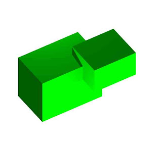
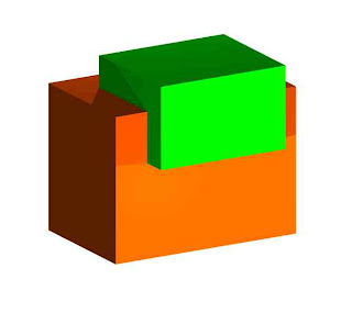
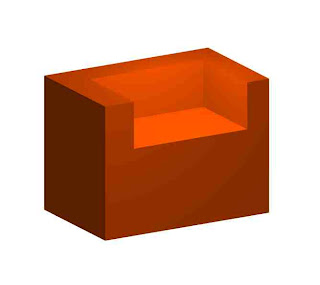
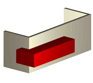
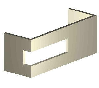
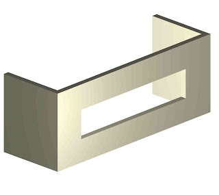
Shell Solid Tool 1
Shell Solid Tool:
Often you will want to edit an object by 'opening it up'. For example turning a cube into an open box, a hemisphere into a bowl or even an extruded polygon into a floor and set of walls!
To do this we can use the Shell Solid Tool. In the Mode Bar set the Shell Preferences to the desired thickness and also select either 'Shell Inside' or 'Shell Outside'.
Select the face to shell and in the Mode Bar select the Green Tick Button to complete the command.
We can always change the thickness of the shell in the Object Info. Palette afterwards.
We can shell very complex shapes but make sure that you save your work first just in case the computer cant take it and crashes!


3D Fillet Tool
Once we have created 3D objects there are many tools to edit and refine them further. These are also located in the 3D Modeling Menu in the Tool Sets Palette. There are too many to go through today but we will look at the main ones that I think you will need to use.
Fillet Edge Tool:
Most 3D objects do not have perfect sharp edges but are instead smoothed off with a fillet edge. Placing these onto objects will add extra detail and quality to your model and help the renders achieve greater realism.
Note that in the Mode Bar we can set the Fillet edge Preferences. Firstly set the fillet Radius and secondly whether to fillet either a single Edge or a whole Face.
Select the edge or face that you wish to fillet and in the Mode Bar select the Green Tick Button to complete the Command. Note that by holding down the shift key we can select multiple edges or faces to fillet.
It is a good idea to wait and go through your model at the end of a project and place fillets on the relevant edges.
You may also need to use the fillet tool more radically to alter the form of an object. We can turn a cylinder into a pill shape or even a sphere if we place a big enough fillet.
The Fillet Radius can be altered afterwards in the Object Info. Palette. To take a fillet off an object we need to select it and go to Modify> Ungroup.

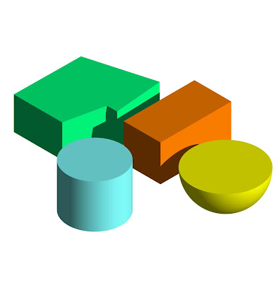
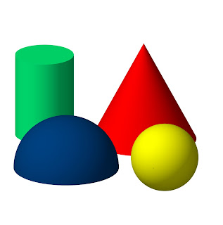
Creating 3D Primitives
Last week we looked at taking 2D shapes and giving them an extrusion value using the Model> Extrude tool. Vectorworks also has many 3D Primitives which does this process in one simple step. There are also tools which create 3D shapes not possible through Linear extrusion, such as cones, spheres and hemispheres.
To model using 3D Primitives go to the 3D Modeling Menu in the Tool Sets Palette.
Cylinders and Cones (By Radius Mode):
Select the view you require and click to determine the objects center point. The computer will then ask you to input a height value (this can always be changed later either manually or through the object Info. Palette). Next drag the mouse out to determine the radius of the Primitive.
Spheres and Hemispheres (By Radius mode):
Click to determine the objects center point, drag the mouse out to determine the objects radius, click again to complete the command. Hemispheres will be drawn with the flat surface at the base, to rotate go to the required view and use the Modify>Rotate> Flip Vertical /Horizontal Commands.
As with all tools, have a go at the different modes of drawing available in the Mode Bar.
Extruded Rectangle / Extruded Polygon:
Click to determine a corner point of the object, input the height value required and then drag and draw to complete the object. Remember to double click to finish Extruded Polygons.
Editing Primitives:
3D Primitive Rectangles and Cylinders act just like extruded 2D Primitives. we can double-click on them and 'go inside' the extrusion. We can now edit the shape, add surface, clip surface etc.
Editing Extruded Polygons is done slightly differently. You will notice that they are called 'Meshes', this means that instead of being one solid object they are made up of many seperate 3D Polygons. Double-click on the Mesh and we can now edit individual planes. Each plane can be given a different colour, or we can delete, resize or move individual planes.
To model using 3D Primitives go to the 3D Modeling Menu in the Tool Sets Palette.

Cylinders and Cones (By Radius Mode):
Select the view you require and click to determine the objects center point. The computer will then ask you to input a height value (this can always be changed later either manually or through the object Info. Palette). Next drag the mouse out to determine the radius of the Primitive.
Spheres and Hemispheres (By Radius mode):
Click to determine the objects center point, drag the mouse out to determine the objects radius, click again to complete the command. Hemispheres will be drawn with the flat surface at the base, to rotate go to the required view and use the Modify>Rotate> Flip Vertical /Horizontal Commands.
As with all tools, have a go at the different modes of drawing available in the Mode Bar.
Extruded Rectangle / Extruded Polygon:
Click to determine a corner point of the object, input the height value required and then drag and draw to complete the object. Remember to double click to finish Extruded Polygons.
Editing Primitives:
3D Primitive Rectangles and Cylinders act just like extruded 2D Primitives. we can double-click on them and 'go inside' the extrusion. We can now edit the shape, add surface, clip surface etc.
Editing Extruded Polygons is done slightly differently. You will notice that they are called 'Meshes', this means that instead of being one solid object they are made up of many seperate 3D Polygons. Double-click on the Mesh and we can now edit individual planes. Each plane can be given a different colour, or we can delete, resize or move individual planes.

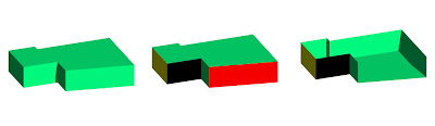
Boolean Operations
We have looked at many ways of creating 2D forms from multiple 2D shapes using Add/Clip Surface. In Vectorworks you can also create objects by using two 3D objects as your starting point, this is what we term Solid Modeling.
Model Menu 2:
Select two or more overlapping solids and use the Model >Add solid command to combine into one new ‘Solid Addition’.
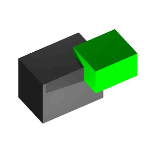
Select two overlapping solids and use the Model >Subtract Solid command to create one new ‘Solid Subtraction’.
You can edit a Solid Addition/Subtraction by double-clicking on the object. Once 'inside' you can move the individual objects around and also edit the forms of the individual solids.
To add to/subtract further from an Addition/Subtraction it is not needed to repeat the process using the Model menu. You can simply model the extra objects 'inside' the Addition/Subtraction and the computer will do the job for you. Exit the Addition/Subtraction to see the results.
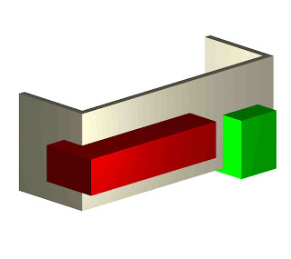
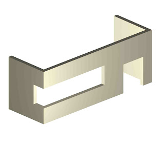
To cut a hole right through a 3D object make sure that the 'cutter' object extrudes past the edges of the other object. It does not matter how far as long as it does!
Try out the Model >Intersect Solids and Model >Section Solids commands.
Model Menu 2:
Select two or more overlapping solids and use the Model >Add solid command to combine into one new ‘Solid Addition’.


Select two overlapping solids and use the Model >Subtract Solid command to create one new ‘Solid Subtraction’.


You can edit a Solid Addition/Subtraction by double-clicking on the object. Once 'inside' you can move the individual objects around and also edit the forms of the individual solids.


To add to/subtract further from an Addition/Subtraction it is not needed to repeat the process using the Model menu. You can simply model the extra objects 'inside' the Addition/Subtraction and the computer will do the job for you. Exit the Addition/Subtraction to see the results.


To cut a hole right through a 3D object make sure that the 'cutter' object extrudes past the edges of the other object. It does not matter how far as long as it does!
Try out the Model >Intersect Solids and Model >Section Solids commands.
SESSION 5 : Solid Modelling
DAY THREE: Checklist
Boolean Operations:
Add Solid Command
Subtract Solid Command
Editing Solid Additions / Solid Subtractions
Intersect Solid Command
3D Primitives
Cones, Spheres, Cylinders and Hemispheres
Extruded Rectangles, Extruded Polygons
Editing Primitives
De-Forming Primitives
3D Editing Tools 1
Fillet Tool Settings
Shell Solid Tool
Un-Grouping Fillets and Shells
Monday
EXERCISE 04 : MODEL ORGANIZATION


This time we will construct the building using the wall tool instead of extruded 2D primitives!
- Again make a new Layer (Walls).
- With the 3D Model Layer showing with Snapping Enabled start to draw the straight wall sections (first set the wall thickness to 200mm)
- Next draw the curved section of the wall using the Wall by Radius Mode. We can use the center point of the circle in a layer below as a start point.
- Set the z Heights for the walls.
- You may need to join any walls that are Un-joined.


Sunday
Working with Layers 2
Layer Visibility:
You can use Layer visibility settings to add interest when presenting your work, we will use Layer Visibility settings in todays Exercise to present our model in several different states.
You can use Layer visibility settings to add interest when presenting your work, we will use Layer Visibility settings in todays Exercise to present our model in several different states.
- To see other layers whilst in a layer go to View >Layer options. Here we can select how to see the other layers.
- Active Only: Only the present Layer is visible.
- Show others: The other layers are seen but not editable.
- Gray Others : The other layers are grayed but not editable.
- Show/Snap Others: The other Layers are visible and act as snap points when drawing.
- Gray/Snap Others: The other Layers are grayed and act as snap points when drawing.
- Show/Snap/Modify Others: You are able now to modify other layers from this layer!
- Each layer will be shown in its selected orientation, scale and level of render. To align all other layers orientation to match the present layer go to View >Align Layer Views.
- To adjust individual layer visibility go to Tools>Organization>Design Layers, select the layer and click in the relevant visibility column (visible, gray or invisible) .
- This can also be done through the Navigation Palette.
Doors and Windows
Vectorworks has what are termed Hybrid Objects. These objects can look different in 2D and 3D, making them perfect for both architectural plans as well as visualisations. Vectorworks doors and windows are Hybrid objects, for example in plan view a door will show an arc for opening radius but act just like any other object in a 3D view.
Plug-Ins:
The Resource Browser contains many ‘Plug-Ins’ for your Vectorworks model.
Vectorworks has a huge library of pre-built door and window objects which correspond to real-life manufacturing standards. To activate a plug-in simply select it and drag into the drawing space.
If you know exactly which door or window you require then this is very useful, today however we will be looking at making our own from the default window and door symbols (These can also be found in the Building Shell Pallette).
Doors and windows can be snapped into walls and then repositioned in plan view by selecting the plug-in at one of its ends and moving it along the wall (make sure you use the double-headed angled arrow cursor).
Using the Object Info Palette we can now adjust settings such as height, width and configuration (along with the option of having a door open or closed in 3D). You can also adjust the elevation height of a window.
Extra editing controls are accessed by double-clicking on the plug-in object. This will open up a large box with a number of different tabs. Here you can adjust in more detail the makeup of the object (For example you can adjust the thickness of a sill or add a door threshold).
Floors and Ceilings
2D Floor Areas
- Drawing the Floor Area:
It is usually best practice to draw the floor area
first and then use this as a guide around which to construct the walls. This is
especially useful when modeling one room for visualisation. You may have done a
site survey and have all of the internal measurements, in this case it is
easier to construct an accurate 2D shape rather than straight away determine
the individual lengths of multiple walls.
- · We can draw the floor area in two ways, either as a set of individual lines, which trace the outline of the room or as a set of shapes which do the same. As we looked at in session 2 these shapes can be then added together to show the complete internal room area.


- · When drawing walls around the Floorplan template make sure that you use the appropriate drawing mode selected from the mode bar.
- · You do not want to have your walls sitting inside the floor area if you have spent time drawing it out accurately!
- Using the AEC Command: Vectorworks has inbuilt commands which can be used for quick and easy construction of walls and floors. They are located in AEC>Architectural menu.
The Create Polys from Walls command can be used to create flooring and ceilings from multiple walls. Select all of the walls that form contained spaces and access the command (Note that you must select wall objects only for the command to work). Select either Gross or net (room) Polys and see the results.
It is useful to first group all of the polygons created so that they can be edited easily. Enter the group , they can now be extruded either individually or together. The benefit of extruding individually is that they can all have separate textures applied.
The Create Walls from Polys Tool takes a polygon and constructs walls around it. The polygon can include curved points but the program may have trouble with excessively complex shapes.
The curved part of the polygon will produce curved walls made up of many individual straight walls. This is different to the curved wall tool which is made of a single wall. This means that it is trickier to position symbols into the wall where desired.
The Floor shapes that you construct can often simply be duplicated and moved up to act as your ceiling object as well!
Drawing and Editing Walls
·
Drawing
and Editing Walls
Up to now we have looked at drawing walls using 2D
shapes (e.g Double Line Polygon Tool or an Off-Set Floor Area as in Session 2).
Vectorworks however has a set of advanced Tools
to draw Walls.
The Building Shell (Green Roofed building Icon) is found in the Tool Sets Palette and contains all of the tools needed to construct and edit walls in Vectorworks.
Straight Wall Tool:
The Building Shell (Green Roofed building Icon) is found in the Tool Sets Palette and contains all of the tools needed to construct and edit walls in Vectorworks.
Straight Wall Tool:
This tool works by clicking and moving the mouse to determine the length and angle of the wall.
- To draw a single wall, click, drag and then double
click to finish.
- You may draw multiple walls at one time, simply
click once and then continue to draw a second wall length. Double-Click as
normal to finish. They will all be selected once you have finished drawing
them, this makes it easy to give them heights and attributes quickly.

The lengths of walls can be adjusted in two ways:
- manually by dragging one end of the wall to a new position. Take care to select the correct cursor (double-headed arrow, angled cursor).
- or in the Obj Info. Palette. Adjust the L value, found under the polar co-ordinates settings. (Note that we can also change the angle of the wall here as well).

We can also Re-position both the end and centre points
of a wall on the grid using the x/y settings in
the Object Info. Palette. Make sure that you select the appropriate point on
the Box position Indicator.
Saying this though, it is always better to have guide lines to use when drawing walls!!!
Saying this though, it is always better to have guide lines to use when drawing walls!!!
The Object info Palette also contains controls for these other settings:
- +Z : Sets the overall height of the wall.
- Bot Z : Sets the height that the wall starts at (Can be both positive and negative).
- Thick : Sets the thickness of the wall (If changed the wall will alter from its center-line).
- Caps : Draw lines to 'cap' the start and end of a wall. This is for 2D work only, wall ends will always be solid in 3D.
- Type: Set the Caps to be either Round or Flat.
This tool has many modes and requires a bit of practice to understand but acts just like the straight wall tool in many respects.
Wall Join Tool:

New walls can be ‘snapped’ into existing ones at any angle and also at corner points. However for more complex wall operations we use the Wall Join Tool.
There are five modes to this tool and each one corresponds to a particular situation, use the diagrams as clues. They all work by clicking on one wall and then drawing a line to the wall to join to. It makes a difference which wall is selected first so if the result is not what you expected try again in another order.
Fillet Tool (Basic Palette):


Use the fillet tool to produce rounded corners to two walls that meet each other. Select the Fillet mode and Set the Fillet Preferences in the mode bar. In top view click on one wall and then on the second.
Try out the three settings for different results. The Fillet can be either 'external' or 'internal'.
Individual and multiple walls can be picked up and moved and you will find that it is often useful to nudge them into place by holding down shift and using the arrow keys.
Take care when editing walls, to lengthen, rotate and move walls requires different cursors. Get to know them and have patience at first when trying to find a particular one!
Subscribe to:
Posts (Atom)