Monday

Exercise 02+: Seat Profile 3D


3D Modelling


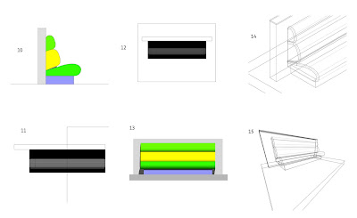
  • Base Section =2400mm


  • Seat sections = 2500mm


  • Wall Section = 3000mm


  1. At this stage save your work, make a new layer (Name 3D model), and copy and paste a copy of the complete 2D profile into the new layer.


  2. With the profile copy we can now extrude each part individually to the correct length (First go to the left side view, number 4 on the keyboard number keys). Notice that all of the extrusions extrude from x=0.


  3. In top view (0), select all the extrusions and align using Modify>Align.


  4. This is how the seat looks in front elevation


  5. Use the 3D Fillet edge tool (Tool sets Palette) to smooth the ends of all the seat sections.


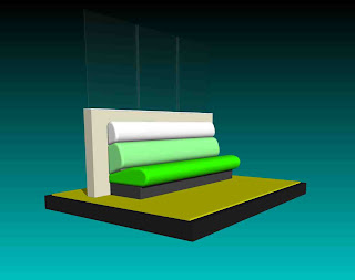
  6. Have a look at the model in 3D. Try out a few different types of Render!
Below is how the seat model will look after we have added some glazed panels to the top of the wall and applied a few lights to the scene.


Exercise 01 : 2D Floorplan


The first exercise we will look at covers the basics of 2D drawing and the transformation tools we have looked at in session two. You will produce a 2D floorplan of an imaginary nightclub. Next week we will take this plan and turn it into a 3D solid model.

It is possible to produce plans, sections and elevations directly from a 3D model, however sometimes it is easier and quicker to keep the 2D and 3D parts separate. It is a useful exercise so try and get it as accurate as possible, the trick to good 3D modelling is in the initial drawing it has to be said, so practice is essential!


----------------------------------------------------------------

2D Attributes

Attributes Pallette (2D)
  • All 2D objects can have their graphic attributes changed whether they are lines, rectangles, polygons or text. 2D objects, unlike 3D objects always show their attributes, this is one of the ways we can tell if an object is still in a 2D state.
  • The attributes palette is used to control the graphic nature of both 2D and 3D objects, but contains certain elements that are only visible in two dimensions. We will concentrate for now on 2D Attributes.
  • 2D Objects are made up of two basic parts:
Fill: This is the internal surface of the 2D object. The Fill can be set to be a
number of differing settings.

1. Solid: Shows the chosen colour attribute always.
2. None: Turns the object surface invisible showing any objects underneath.
This can be useful when aligning two 2D objects.
3. Pattern: Vectorworks has a library of pre-designed patterns to assign to 2D
objects.
4. Hatches: Vectorworks has a library of pre-designed hatches to assign to
objects. This is especially useful when drawing sections and providing keys.
5. Images: Vectorworks has lots of image files to use on your 2D surfaces, most
of these are building textures and materials (e.g tiles, brick, turf).
6. Gradient: You can assign surfaces black greyscale and colour gradients.

Pen Line: This refers to the outline of a 2D object and the wireframe of a 3D object. The Pen Line will only show in 3D in Wireframe Render. You can change the colour, thickness and style of the Pen Line to produce realistic plans, sections and elevations.

1 As well as using Vectorworks own pre-set attributes it is possible to design your own. This is done through the Resource Browser Palette.

2 Open up the New Resource tab and you will see a list of options relating to attributes and rendering. For example by choosing New Renderworks Image you can import a pre-saved image file to create your own Image. This may be a photograph, a scanned texture or drawing.

3 Once created you can apply the Image to any 2D surface. Simply select the
surface, locate the Image

Selecting Objects

To modify an existing object you must first select it. There are a number of ways to select a single or group of objects, some of which work as in other Macintosh and Windows graphics applications.

Object pointing

When you select an individual object with the selection tool(x) and click the mouse. You will know it is selected as it will have selection handles and now have an orange outline. It now will also display its own set of attributes in both the Object Info Palette and the Attributes Palette.

Shift clicking

Single-clicking on an object allows only one object at a time to be selected. If the shift key on the keyboard is pressed then multiple objects can be selected. The shift key can also be used to combine marquee selections (see below) and de-select one or more objects from a group of selected objects.

Selection marquee (type A)

The selection tool (x) can also be used to drag a rectangular marquee completely over a group of objects. All objects contained within will be selected.

Selection marquee (type B)

If the selection tool is used to drag a rectangular marquee over a group of objects while the option or alt key is pressed, all objects that are contained, even partly, within the marquee are selected.


`
Type A Type B

Select all

To select all the objects within a drawing file pick the select all command from the file menu (Ctrl A / Command A).

De-selecting all

To de-select all the objects within a drawing file double click on the 2D selection tool, or click in ‘dead space’ within the drawing space.

Transformation Operations


2D Drawing Primitives

This section lists all the major 2D Primitives that are used to produce a drawing. 

Once drawn they can be manipulated and edited in various ways to suit the needs of the draftsman or designer. Subsequent notes will explain these processes.

 
Lines
Double Lines 
Rectangles (Normal /  Rounded / Rotated) .
Circles
Ovals


Arcs
Polylines
Polygonsregular polygons, irregular polygons, and double-line polygons.


Each drawing tool has extra options in the Mode Bar

These generally include different ways of drawing the object and preferences for setting dimensions and seperation values.

SESSION 2 : 2D Drawing Basics

Modifying 2D objects
-Selecting objects (Marquee and lasso)
-Moving objects,
-Sending objects
-Repositioning Objects on the page.
-Resizing objects (Selection tool, Tab Key and Object Info Palette)
-Transformation Operations
-Add and Clip Surface tool

2D Attributes
-Pen and Fill Colours
-Line styles and thickness

Re-Shaping polygons
-Move Vertex Mode
-Change Vertex Mode

Exporting 1
-Exporting to scale
-Exporting as PDF

Work Organization
-Creating New Layers
-Importing Images
-Creating Folders
-Naming and placing your saved work
-Required Course outcomes

Command and Data Entry

To create objects in Vectorworks you must first select the drawing tool  you wish to use and then input data for the computer to draw the object.

Tools can be selected in two ways:

1. By clicking on their icon:

All the basic drawing tools (line, arc, rectangle, ellipse, etc.) are represented by icons on the tool palettes. Two-dimensional tools are contained within the Basic palette, three-dimensional tools are contained within the Tool Sets palette. To activate a tool simply click on its icon.

2. By using a keyboard shortcut:

All of the tools on the Basic palette have corresponding keyboard shortcuts. Pressing x returns to the 2D Selection tool. A full list of keyboard shortcuts is contained below.


Data (dimensions etc.) is entered into Vectorworks after the drawing tool has been selected. It can be entered in a number of ways.

1. By drawing with the mouse:

When drawing a line, for example, the mouse can be used to specify the start and end point. Select the line tool, click once with the mouse to specify the starting point of the line and click again to specify the end point.

2. By using the  Data display bar:

When drawing an object you can use the data display bar to type in exact dimensions and co-ordinates. To use the data display bar to draw a line, first pick the line tool. Next hit the tab key on the keyboard to access the first field in the blue display bar. To move to the next field press tab again, or enter data and press return.

3. By double clicking on a tool icon:

If you double-click on a tool icon a dialogue box will appear allowing the exact location and dimensions of an object to be specified.


Accurately Re-Sizing objects

1. Manually using the Mouse:

With the 'Angled, Double Headed Arrow' Selection cursor you can resize an object by dragging any of its corner or mid points around. Note that with the shift key held down the object will resize and stay in proportion.

2.By using the Object Information palette:

Discussed on separate notes below.


Moving Around a Drawing

The Basic palette contains the pan, zoom in, zoom out and page move tools.


The pan tool is used to 'grab' your drawing and move it around the screen, changing what piece of it displays in the drawing window. To use the tool select it, move the cursor into the drawing window (the arrow cursor will change into a hand) and click and drag.

The page move tool changes your drawing position on the representation of the printed page visible on the screen. To use the tool select it (from the pull-out menu under the pan command), move the cursor into the drawing window and drag.

The zoom in tool works in two ways. Firstly, double-clicking on the tool doubles the magnification of your drawing. Secondly, the zoom in tool can be used to view a small portion of your drawing by dragging a marquee over it.

The Views bar (below) contains a number of tools for zooming around your drawing as well as options for saving views of your drawing.


A. Back: Click this icon to go to the previous saved sheet.
B. Forward: Click this icon to go to the next saved sheet.
C. Zoom in: This works just like the zoom in tool on the Basic palette.
D. Zoom out: This works just like the zoom out tool on the Basic palette
E. Normal scale: Click this icon to display your drawing in its real-world scale.
F. Fit to window: This command gives you an easy way to quickly display your whole page in the drawing window.
G. Fit to objects: This option causes Vectorworks to display the objects that are selected in the drawing with the largest possible screen.
H. Saved Views Menu: Access to saved sheets and views (Discussed in later notes).

Setting Up a New Document

When working on a drawing in Vectorworks you should first set the units, proposed paper scale, grid set-up and paper size. These drawing properties can be changed at a later date but it is useful to set them from the outset.

All of these can be set from one central place. Go to File > Document Settings > Document Setup.

Units
Vectorworks enables users to use whatever units they prefer. The most common units such as millimetres and feet / inches are predefined but users can also create their own units. The vast majority of CAD users in the UK use millimetres. Set the unit type to millimetres by picking it from the pull-down list and ensure display as decimal is selected.


Scale

When you draw objects in Vectorworks they are drawn at full-size but displayed on screen (and printed) to scale (known as paper scale). When a new Vectorworks document is created a default sized piece of paper (usually A4) is represented on screen and the default paper scale (usually 1:1 or 1:50) is automatically used.

NB: In Vectorworks you have the flexibility of setting one scale for all the layers in your drawing, or setting a different scale for individual layers. This enables printed drawings to have elements at different scales (maybe a detail at 1:10 and a plan at 1:50).


Paper size
Go to the Menu Bar and choose File > Page Setup. Next, click on the Printer Setup button and choose the settings for your printer. Click on the OK button and then check the Page Setup. You should have one page horizontal and one page vertical.

Here we can specify the size (A3, A2 etc) and orientation of your document (Portrait or landscape). To specify a paper size when printing, Vectorworks enables smaller sheets of paper to be tiled together in order to create large drawings.


Set Grid
Vectorworks drawing is done to a pre-set grid of points and lines on the page that can be changed at any stage .

The Reference grid is shown as blue vertical and horizontal lines on the page which can never be smaller in interval than the snap grid.

The Reference lines correspond to the rulers running along the top and left edge of the page, starting from lines at X=0 and Y-0 and then repeated at your pre-set intervals.

By default the Reference lines will not print with your work. This can be changed through the Set Grid dialogue box, a really useful option if you wish to draw over any printed plans for example.

The snap grid consists of points that can be set to any level of interval from 0.1mm up to 10000mm and beyond.

The Snap Grid limits the freedom of any drawing to that selected grid. This is really useful for drawing to standardised measurements and limit’s the need to edit object dimensions after drawing. Select the appropriate snap grid for the task in hand. You can alter the grid settings during a project and this will not affect any objects drawn.


Reference Grid = 1000mm / Snap Grid = 500mm

Vectorworks Screen Interface


Vectorworks 12.5 Screen Interface

1. Menu bar
This bar lets you access all of Vectorworks commands. These are grouped in pull-down menus. The commands shown change depending on the workspace you are in. Here you can also access Vectorworks Help and Tutorials

2.Title bar
Each window on a computer has a title bar. This bar can be used to reposition a window (ie. drawing window or palette) by clicking on the bar, holding down the mouse and dragging the cursor.

3. Data display Bar
This bar displays data about the drawing file you are working on and objects within it. Unless you are drawing an object the bar stays in default mode. In default mode the bar shows the current position of the cursor (X and Y), the current class, layer and zoom percentage. Also note that in this mode the data display bar contains pull-out menus for both classes and layers.

When you are drawing an object Vectorworks changes the data display bar to drawing mode so that you can type in the exact dimensions and coordinates of the object you are drawing rather than using the mouse (use the tab key). Depending on what drawing tool you are using, the bar displays different fields.

4. Mode bar
When one of Vectorworks tools is selected, its name is listed in the mode bar. If the tool has more than one mode, the mode bar will display a button for each mode available. If the tool can use pre-set preferences you can set these through the furthest button to the right on the mode bar.

5. Views bar
The views bar enables users to quickly zoom around their drawing file as well as quickly framing an object or page on the screen. It also allows users to save individual views of a drawing (known as sheets).

6. Page and grid
Each Vectorworks drawing window contains a grey outline of the drawing page size. This page may contain a grid if the grid option is turned on (both Snap and Reference).

7.Palettes
Vectorworks has palettes that can be displayed or hidden in your drawing window (Basic, Tool Sets, Attributes, Object info etc). A combination of these palettes will appear when you select a particular workspace. If you need to use a palette and it is not visible on screen, select it from the window pull-down menu.

To make sure we are all looking at the same set of tools and commands, go to the Menu bar: Choose Tools > Workspaces > Standard

SESSION 1 : Getting Started

Vectorworks: Digital Modelling for Architectural Environments

DAY ONE: Checklist

Resources
-DMAE Blog and Internet sites
-Vectorworks Help Menu
-Tutorials for download
-Each other


Getting Started:
-Vectorworks Interface
-Palettes
-Menu bar, data display bar, mode bar, views bar
-Page, grids and rulers
-Layer Scale
-Units
-Set Grid (Snap and Reference)
-Print Setup
-Workspaces
-Keyboard shortcuts


2D Tools Palette
-Primitives (Lines, rectangles, ellipses, arcs)
-Double Line Polygons
-Setting Preferences and using Modes

----------------------------------------------------------------

Course Documentation


SCHEME OF WORK

VECTORWORKS 2008: DIGITAL MODELLING FOR ARCHITECTURAL ENVIRONMENTS

DAY ONE: Produce a 2D Floorplan

GETTING STARTED
Learn how to set up a new document.
Get to know and customise the screen environment and interface.
Understand the theory of co-ordinates, measuring and scale.

2D DRAWING PRODUCTION
Learn to create and edit 2D shapes and to place with precision.
Familiarize yourself with the basic 2D Transformation operation Tools.
Learn how to export material from Vectorworks to scale.

DAY TWO: Produce a Rendered 3D Interior

3D ENVIRONMENT
Create new 3D forms through linear extrusion.
Learn to arrange/move/Duplicate objects in 3D space.
Learn to navigate around your model in Isometric and Perspective.

HYBRID OBJECTS
Learn to use and customise Vectorworks Wall Tools.
Learn to add and edit Vectorworks Plug-Ins to your model.
Understand Layers and Layer Visibilities.

DAY THREE: Produce a 3D Model of multi-story building.

ORGANIZATION
Look at how to set up a model over several floors.
Learn to use Classes effectively for Presentation.
Learn Effective use of Duplicates and Symbols.

SOLID MODELLING
Practice Boolean operations
Look at Shelling, Filleting, Projecting etc.
Create Backgrounds and Image props for your models

DAY FOUR: Produce Furniture/Exhibition Stand Models

2D DRAWING PRODUCTION II
Import plans and sections into Vectorworks to use as guides.
Create and reshape polygons and polylines.
Take advanced 2D profiles and turn them into 3D Sweeps

ADVANCED EXTRUSIONS
Look at Multiple Extrudes
Look at NURBS Modelling using the Loft Surface Tool
Explore the possibilities of Path Based Modelling.

DAY FIVE: Advanced Visualisation

SHEET LAYERS
Learn to produce 2D and 3D Viewports.
Learn to produce Plans, Sections and Elevations from your 3D model.
Learn to produce Rendered Bitmaps of your Model

ANIMATIONS AND EXTRAS
Render a simple orbit or path based animation of your model.
Compile all course work into a PDF document.
Look at other compatible 3D software.