Sunday

Exercise 05 : Chromogenic Dwelling Exterior


Download the Worksheet above for step-by-step instruction.


Download the Simplified Elevation above for Importing into Vectorworks


http://www.beigedesign.com/proj_chromogenic.html

Below is an example of the model rendered in perspective with a background applied.

---------------------------------------------------------------

Shell Solid Tool 1

Shell Solid Tool:
Often you will want to edit an object by 'opening it up'. For example turning a cube into an open box, a hemisphere into a bowl or even an extruded polygon into a floor and set of walls!

To do this we can use the Shell Solid Tool. In the Mode Bar set the Shell Preferences to the desired thickness and also select either 'Shell Inside' or 'Shell Outside'.

Select the face to shell and in the Mode Bar select the Green Tick Button to complete the command.

We can always change the thickness of the shell in the Object Info. Palette afterwards.

We can shell very complex shapes but make sure that you save your work first just in case the computer cant take it and crashes!

3D Fillet Tool

Once we have created 3D objects there are many tools to edit and refine them further. These are also located in the 3D Modeling Menu in the Tool Sets Palette. There are too many to go through today but we will look at the main ones that I think you will need to use.

Fillet Edge Tool:
Most 3D objects do not have perfect sharp edges but are instead smoothed off with a fillet edge. Placing these onto objects will add extra detail and quality to your model and help the renders achieve greater realism.

Note that in the Mode Bar we can set the Fillet edge Preferences. Firstly set the fillet Radius and secondly whether to fillet either a single Edge or a whole Face.

Select the edge or face that you wish to fillet and in the Mode Bar select the Green Tick Button to complete the Command. Note that by holding down the shift key we can select multiple edges or faces to fillet.

It is a good idea to wait and go through your model at the end of a project and place fillets on the relevant edges.

You may also need to use the fillet tool more radically to alter the form of an object. We can turn a cylinder into a pill shape or even a sphere if we place a big enough fillet.

The Fillet Radius can be altered afterwards in the Object Info. Palette. To take a fillet off an object we need to select it and go to Modify> Ungroup.

Creating 3D Primitives

Last week we looked at taking 2D shapes and giving them an extrusion value using the Model> Extrude tool. Vectorworks also has many 3D Primitives which does this process in one simple step. There are also tools which create 3D shapes not possible through Linear extrusion, such as cones, spheres and hemispheres.

To model using 3D Primitives go to the 3D Modeling Menu in the Tool Sets Palette.

Cylinders and Cones (By Radius Mode):
Select the view you require and click to determine the objects center point. The computer will then ask you to input a height value (this can always be changed later either manually or through the object Info. Palette). Next drag the mouse out to determine the radius of the Primitive.

Spheres and Hemispheres (By Radius mode):
Click to determine the objects center point, drag the mouse out to determine the objects radius, click again to complete the command. Hemispheres will be drawn with the flat surface at the base, to rotate go to the required view and use the Modify>Rotate> Flip Vertical /Horizontal Commands.

As with all tools, have a go at the different modes of drawing available in the Mode Bar.

Extruded Rectangle / Extruded Polygon:
Click to determine a corner point of the object, input the height value required and then drag and draw to complete the object. Remember to double click to finish Extruded Polygons.

Editing Primitives:
3D Primitive Rectangles and Cylinders act just like extruded 2D Primitives. we can double-click on them and 'go inside' the extrusion. We can now edit the shape, add surface, clip surface etc.

Editing Extruded Polygons is done slightly differently. You will notice that they are called 'Meshes', this means that instead of being one solid object they are made up of many seperate 3D Polygons. Double-click on the Mesh and we can now edit individual planes. Each plane can be given a different colour, or we can delete, resize or move individual planes.

Boolean Operations

We have looked at many ways of creating 2D forms from multiple 2D shapes using Add/Clip Surface. In Vectorworks you can also create objects by using two 3D objects as your starting point, this is what we term Solid Modeling.

Model Menu 2:

Select two or more overlapping solids and use the Model >Add solid command to combine into one new ‘Solid Addition’.

Select two overlapping solids and use the Model >Subtract Solid command to create one new ‘Solid Subtraction’.

You can edit a Solid Addition/Subtraction by double-clicking on the object. Once 'inside' you can move the individual objects around and also edit the forms of the individual solids.

To add to/subtract further from an Addition/Subtraction it is not needed to repeat the process using the Model menu. You can simply model the extra objects 'inside' the Addition/Subtraction and the computer will do the job for you. Exit the Addition/Subtraction to see the results.


To cut a hole right through a 3D object make sure that the 'cutter' object extrudes past the edges of the other object. It does not matter how far as long as it does!

Try out the Model >Intersect Solids and Model >Section Solids commands.

SESSION 5 : Solid Modelling

DAY THREE: Checklist

Boolean Operations:
Add Solid Command
Subtract Solid Command
Editing Solid Additions / Solid Subtractions
Intersect Solid Command

3D Primitives
Cones, Spheres, Cylinders and Hemispheres
Extruded Rectangles, Extruded Polygons
Editing Primitives
De-Forming Primitives

3D Editing Tools 1
Fillet Tool Settings
Shell Solid Tool
Un-Grouping Fillets and Shells

---------------------------------------------------------------

Examples

Monday

EXERCISE 04 : MODEL ORGANIZATION


This time we will construct the building using the wall tool instead of extruded 2D primitives!
  1. Again make a new Layer (Walls).
  2. With the 3D Model Layer showing with Snapping Enabled start to draw the straight wall sections (first set the wall thickness to 200mm)
  3. Next draw the curved section of the wall using the Wall by Radius Mode. We can use the center point of the circle in a layer below as a start point.
  4. Set the z Heights for the walls.
  5. You may need to join any walls that are Un-joined.


---------------------------------------------------------------


Sunday

Working with Layers 2

Layer Visibility:
You can use Layer visibility settings to add interest when presenting your work, we will use Layer Visibility settings in todays Exercise to present our model in several different states.
  • To see other layers whilst in a layer go to View >Layer options. Here we can select how to see the other layers.
  1. Active Only: Only the present Layer is visible.
  2. Show others: The other layers are seen but not editable.
  3. Gray Others : The other layers are grayed but not editable.
  4. Show/Snap Others: The other Layers are visible and act as snap points when drawing.
  5. Gray/Snap Others: The other Layers are grayed and act as snap points when drawing.
  6. Show/Snap/Modify Others: You are able now to modify other layers from this layer!
  • Each layer will be shown in its selected orientation, scale and level of render. To align all other layers orientation to match the present layer go to View >Align Layer Views.
  • To adjust individual layer visibility go to Tools>Organization>Design Layers, select the layer and click in the relevant visibility column (visible, gray or invisible) .
  • This can also be done through the Navigation Palette.

Doors and Windows

Vectorworks has what are termed Hybrid Objects. These objects can look different in 2D and 3D, making them perfect for both architectural plans as well as visualisations. Vectorworks doors and windows are Hybrid objects, for example in plan view a door will show an arc for opening radius but act just like any other object in a 3D view.

Plug-Ins:


The Resource Browser contains many ‘Plug-Ins’ for your Vectorworks model.

Vectorworks has a huge library of pre-built door and window objects which correspond to real-life manufacturing standards. To activate a plug-in simply select it and drag into the drawing space.

If you know exactly which door or window you require then this is very useful, today however we will be looking at making our own from the default window and door symbols (These can also be found in the Building Shell Pallette).

Doors and windows can be snapped into walls and then repositioned in plan view by selecting the plug-in at one of its ends and moving it along the wall (make sure you use the double-headed angled arrow cursor).

Using the Object Info Palette we can now adjust settings such as height, width and configuration (along with the option of having a door open or closed in 3D). You can also adjust the elevation height of a window.

Extra editing controls are accessed by double-clicking on the plug-in object. This will open up a large box with a number of different tabs. Here you can adjust in more detail the makeup of the object (For example you can adjust the thickness of a sill or add a door threshold).

Floors and Ceilings


2D Floor Areas
  • Drawing the Floor Area:
It is usually best practice to draw the floor area first and then use this as a guide around which to construct the walls. This is especially useful when modeling one room for visualisation. You may have done a site survey and have all of the internal measurements, in this case it is easier to construct an accurate 2D shape rather than straight away determine the individual lengths of multiple walls.

  • ·       We can draw the floor area in two ways, either as a set of individual lines, which trace the outline of the room or as a set of shapes which do the same. As we looked at in session 2 these shapes can be then added together to show the complete internal room area.


  • ·       When drawing walls around the Floorplan template make sure that you use the appropriate drawing mode selected from the mode bar.
  • ·       You do not want to have your walls sitting inside the floor area if you have spent time drawing it out accurately!


  • Using the AEC Command: Vectorworks has inbuilt commands which can be used for quick and easy construction of walls and floors. They are located in AEC>Architectural menu.

    The Create Polys from Walls command can be used to create flooring and ceilings from multiple walls. Select all of the walls that form contained spaces and access the command (Note that you must select wall objects only for the command to work). Select either Gross or net (room) Polys and see the results.

    It is useful to first group all of the polygons created so that they can be edited easily. Enter the group , they can now be extruded either individually or together. The benefit of extruding individually is that they can all have separate textures applied.

    The Create Walls from Polys Tool takes a polygon and constructs walls around it. The polygon can include curved points but the program may have trouble with excessively complex shapes.

    The curved part of the polygon will produce curved walls made up of many individual straight walls. This is different to the curved wall tool which is made of a single wall. This means that it is trickier to position symbols into the wall where desired.
These tools are very useful if you need to draw complex floor shapes and don't feel confident drawing using 2D tools!

The Floor shapes that you construct can often simply be duplicated and moved up to act as your ceiling object as well!

Drawing and Editing Walls


·       Drawing and Editing Walls

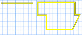
Up to now we have looked at drawing walls using 2D shapes (e.g Double Line Polygon Tool or an Off-Set Floor Area as in Session 2).

Vectorworks however has a set of advanced Tools to draw Walls.

The Building Shell (Green Roofed building Icon) is found in the Tool Sets Palette and contains all of the tools needed to construct and edit walls in Vectorworks.
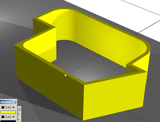
Straight Wall Tool:

This tool works by clicking and moving the mouse to determine the length and angle of the wall.
  • To draw a single wall, click, drag and then double click to finish.
  • You may draw multiple walls at one time, simply click once and then continue to draw a second wall length. Double-Click as normal to finish. They will all be selected once you have finished drawing them, this makes it easy to give them heights and attributes quickly.


The lengths of walls can be adjusted in two ways:
  • manually by dragging one end of the wall to a new position. Take care to select the correct cursor (double-headed arrow, angled cursor).
  • or in the Obj Info. Palette. Adjust the L value, found under the polar co-ordinates settings. (Note that we can also change the angle of the wall here as well).


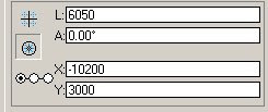
We can also Re-position both the end and centre points of a wall on the grid using the x/y settings in the Object Info. Palette. Make sure that you select the appropriate point on the Box position Indicator.

Saying this though, it is always better to have guide lines to use when drawing walls!!!


The Object info Palette also contains controls for these other settings:
  • +Z : Sets the overall height of the wall.
  • Bot Z : Sets the height that the wall starts at (Can be both positive and negative).
  • Thick : Sets the thickness of the wall (If changed the wall will alter from its center-line).
  • Caps : Draw lines to 'cap' the start and end of a wall. This is for 2D work only, wall ends will always be solid in 3D.
  • Type: Set the Caps to be either Round or Flat.
Curved Wall Tool:
This tool has many modes and requires a bit of practice to understand but acts just like the straight wall tool in many respects.
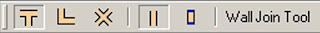
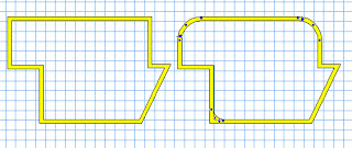
Wall Join Tool:


New walls can be ‘snapped’ into existing ones at any angle and also at corner points. However for more complex wall operations we use the Wall Join Tool.

There are five modes to this tool and each one corresponds to a particular situation, use the diagrams as clues. They all work by clicking on one wall and then drawing a line to the wall to join to. It makes a difference which wall is selected first so if the result is not what you expected try again in another order.


Fillet Tool (Basic Palette):


Use the fillet tool to produce rounded corners to two walls that meet each other. Select the Fillet mode and Set the Fillet Preferences in the mode bar. In top view click on one wall and then on the second.

Try out the three settings for different results. The Fillet can be either 'external' or 'internal'.

Individual and multiple walls can be picked up and moved and you will find that it is often useful to nudge them into place by holding down shift and using the arrow keys.

Take care when editing walls, to lengthen, rotate and move walls requires different cursors. Get to know them and have patience at first when trying to find a particular one!